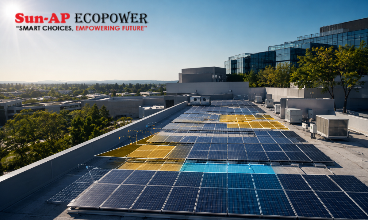
When designing commercial or residential solar arrays, shading solar panels remains one of the most critical yet frequently underestimated challenges facing engineering, procurement, and construction (EPC) contractors.
Even a minor shadow covering a tiny fraction of a single panel can cause a disproportionate drop in total system power output. Authorized Solar panel distributors in India play a pivotal role in mitigating these financial risks by supplying high-efficiency, shade-tolerant module architectures alongside advanced Module-Level Power Electronics (MLPE).
Addressing shading during early project design is essential to protecting system yield and client ROI. Understanding the root cause of shading requires categorizing how shadows interact with a rooftop solar installation:
- Physical Obstructions: External structures such as nearby high-rise buildings, utility poles, overhead power lines, chimneys, and growing tree branches that cast direct, moving shadows across the array throughout the day.
- Environmental Soiling: Accumulated dust, bird droppings, fallen leaves, and industrial particulate matter that block sunlight on localized areas of the panel surface, creating micro-shading conditions.
- Self-Shading from Row Layouts: Inter-row shadows created when front panel rows cast obstructions on adjacent rear rows, particularly during low winter sun angles or on tightly spaced commercial flat-roof installations.
As conventional solar strings are wired in series, a single shaded cell acts like a kinked hose, restricting current flow across the entire electrical string. Working with experienced distribution partners enables solar installers to select specialized equipment designed to isolate shaded sections and preserve overall power generation.
The Electrical Mechanics of Shading With Cell Mismatch and Hotspots
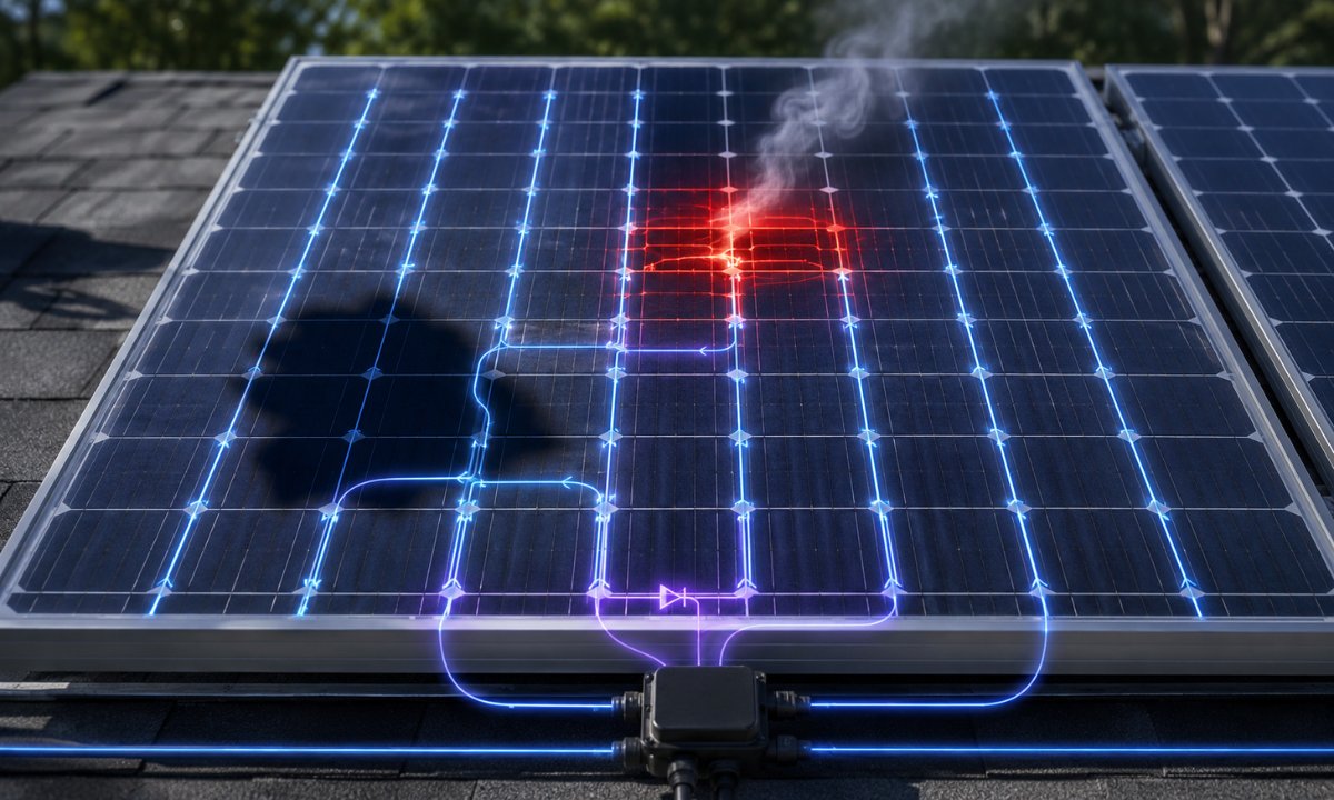
To understand why partial shading causes severe system underperformance, solar engineers must look at the internal electrical wiring of a photovoltaic module.
Standard solar panels consist of individual silicon solar cells connected in series to accumulate voltage. Because series-connected circuits operate at the current level of the weakest cell, shading just one cell limits the electrical current flowing through the entire string.
Common Rooftop Obstacles and Shadow Profiling
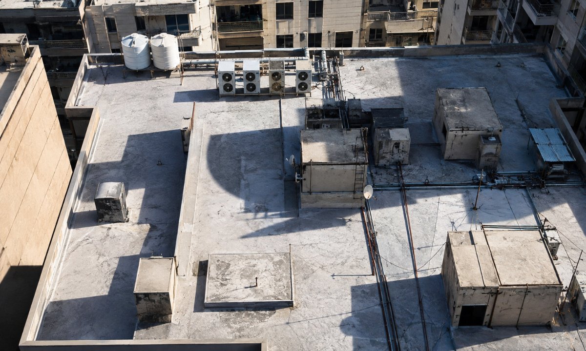
Commercial and industrial (C&I) rooftops across India present unique physical environments with numerous shading hazards. Identifying these hazards during initial site surveys helps engineers design around unavoidable obstructions:
- Parapet Walls and Perimeter Edge Railings: High perimeter walls along building edges cast long, sweeping shadows across adjacent panel rows during morning and late afternoon sun angles.
- HVAC Units and Ventilation Ducts: Large commercial air conditioning units and exhaust ducts cast dense, static shadows that alter shading patterns as the sun traverses the sky.
- Overhead Utility Cables and Water Tanks: Overhead wiring, elevator machine rooms, and rooftop water storage tanks create sharp, concentrated shadow bands across module surfaces.
- Adjacent Structures and Architectural Features: Nearby high-rise buildings or architectural columns create extended shading windows that obscure large portions of the array during specific seasons.
Addressing these rooftop obstacles requires differentiating between near shading and far shading. Near shading involves distinct, hard-edged shadows cast by close objects that block direct solar radiation entirely.
Far shading involves distant horizons or atmospheric haze that reduces diffuse irradiance uniformly without causing severe localized cell mismatches.
The Bottleneck Effect and Thermal Hotspot Formation
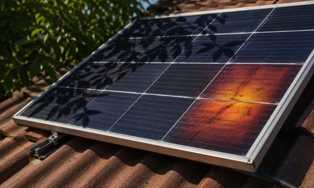
When a solar cell is shaded, it ceases to generate electrical current and transforms into an electrical bottleneck. The unshaded cells in the same series string continue attempting to force current through the shaded cell.
When current is forced through a non-generating cell, the shaded cell becomes reverse-biased. Instead of producing power, it acts as a resistor, absorbing electrical energy from the surrounding unshaded cells and dissipating it as heat. Over extended operational periods, this localized heat buildup creates thermal “hotspots.”
Hotspots cause severe structural and electrical damage over time:
- Solder Joint and Busbar Degradation: Intense localized heating weakens internal solder connections and accelerates metal corrosion inside the module.
- EVA Encapsulant Browning: High thermal stress degrades the ethylene-vinyl acetate (EVA) protective layer, turning it brown and permanently restricting light transmission to the silicon wafer.
- Backsheet Delamination and Micro-cracking: Thermal expansion and contraction stress the protective backsheet, creating moisture ingress pathways and micro-cracks across adjacent cells.
Unmitigated shading losses do more than reduce immediate energy output; they permanently degrade physical module materials, increasing the likelihood of early equipment failure and warranty disputes.
Quantifying Performance Drop and String-Level Efficiency
While physical module degradation poses long-term operational risks, partial shading causes immediate, measurable drops in system output. In conventional string inverter configurations, a single obstructed panel can degrade the output of an entire series string.
Understanding how central inverters and Maximum Power Point Tracking (MPPT) algorithms react during partial shading events allows project developers and EPCs to accurately predict system yield and protect Solar panel efficiency.
The Role of Bypass Diodes in Sub-String Isolation
Standard crystalline silicon PV modules contain internal bypass diodes, typically three per 60-cell, 72-cell, or 108-half-cell module, placed in parallel across sub-strings of cells. When a sub-string experiences partial shade, the reverse bias voltage triggers the bypass diode to conduct current around the shaded cells, isolating them from the rest of the module.
- Conduction Trigger Mechanics: When light irradiance on a sub-string drops significantly compared to adjacent cells, the shaded cells become power consumers. The resulting reverse voltage bias activates the antiparallel bypass diode, allowing string current to pass through the diode rather than forcing through high-resistance shaded cells.
- Voltage Drop Trade-Off: Activating a bypass diode restores full string current flow, but sacrifices the voltage generated by that sub-string (approximately 10V to 12V per sub-string). If a module has one of its three sub-strings bypassed, its power output drops by roughly one-third while string current remains stable.
- Thermal Stress on Junction Boxes: Continuous daily activation subjects bypass diodes to ongoing heat dissipation inside the junction box. Over years of operation, repeated thermal cycling increases diode failure rates, potentially creating permanent short circuits or open circuits that permanently impair module performance.
While bypass diodes prevent catastrophic hotspot damage, relying on them as a primary shade management strategy leads to significant cumulative shading losses.
Inverter MPPT Behavior Under Partial Shading Conditions
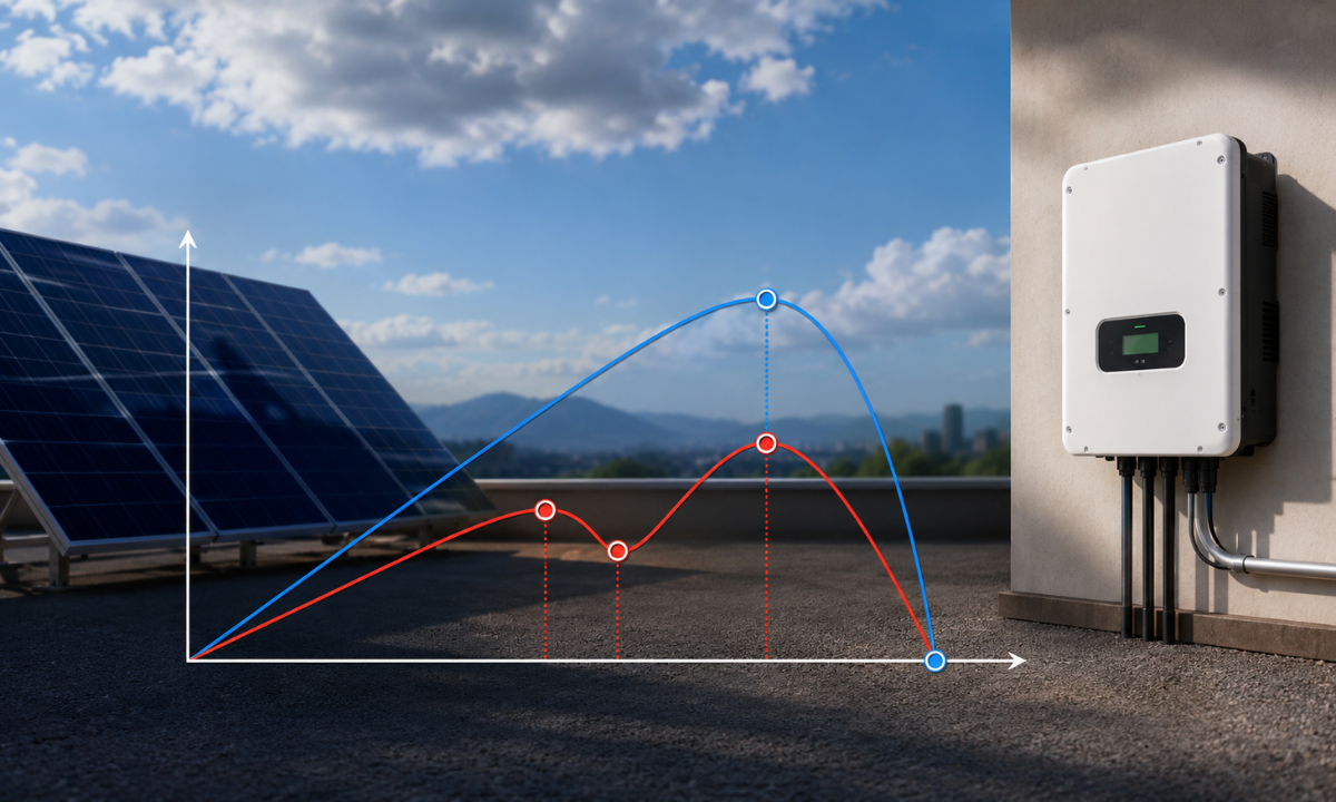
A central or string inverter’s primary task is to dynamically adjust operating voltage and current to maximize instantaneous DC power output using Maximum Power Point Tracking (MPPT).
Under uniform irradiance, the Power-Voltage (P-V) curve of a solar array features a single peak. However, when partial shading activates bypass diodes, the P-V curve distorts into multiple local maximum power points.
| MPPT Tracking Technology | Response to Partial Shading | Impact on Array Power Output | System Yield Preservation |
|---|---|---|---|
| Basic Local MPPT Inverters | Gets trapped at the nearest local peak on the P-V curve | Sacrifices higher global peak power by operating at sub-optimal voltage/current | Low (20% to 50% yield loss across string) |
| Advanced Global Sweep MPPT Inverters | Periodically scans full voltage range to lock onto the global maximum power point (GMPP) | Bypasses shaded sub-strings to maintain high string current at slightly reduced voltage | Moderate (Restores 70% to 85% of available string power) |
| Module-Level Power Electronics (MLPE) | Performs independent MPPT at each module | Operates shaded modules at reduced current while allowing unshaded modules to run at 100% capacity | Maximum (Recovers 95%+ of unshaded potential) |
Choosing inverters equipped with full-curve global MPPT scanning prevents the system from locking onto low-power local peaks, preserving operational efficiency across partially shaded commercial rooftops.
Measuring Cumulative System Output Losses
Quantifying how partial shading scales across an entire commercial rooftop array helps financial analysts and solar engineers model realistic long-term energy generation projections.
To evaluate the operational penalty of unmitigated shading, solar designers categorize output losses into three primary tiers:
- Direct Irradiance Loss: The linear reduction in energy capture caused by physical objects blocking direct sunlight from reaching the silicon wafer surface.
- Mismatch Loss: The non-linear power drop experienced when unshaded modules in a series string are forced to operate at reduced current levels due to a single shaded module’s bottleneck.
- Dynamic MPPT Scanning Loss: The momentary energy generation loss incurred while central inverters perform periodic full-voltage sweeps to re-identify the global peak power operating point.
Factoring these combined loss mechanisms into PVsyst simulations ensures that EPC contractors establish realistic performance guarantees and select appropriate balance-of-system (BoS) hardware during the design phase.
Hardware-Level Mitigation: Half-Cut Cells and Panasonic Innovation
While system-level design and inverter topologies play a vital role in shade management, innovations in solar module manufacturing allow panels to minimize shading losses directly at the cell level. Traditional full-cell panels are vulnerable to partial shading because their cells are wired in a single continuous circuit.
Modern module architectures overcome these limitations by splitting cell circuits, optimizing internal wiring, and introducing advanced semiconductor materials that maintain higher energy yields under diffuse light.
The Mechanics of Half-Cut Cell Architecture
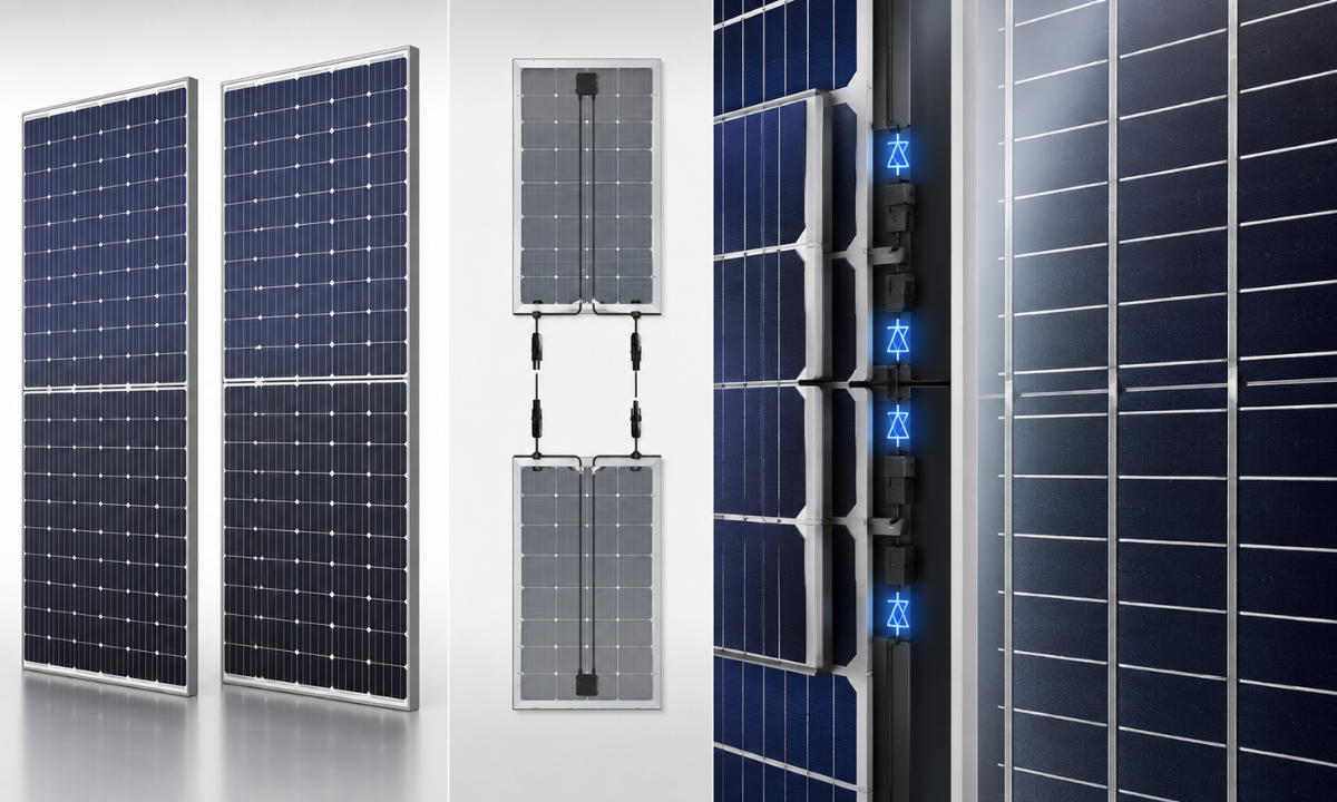
Half-cut cell technology involves cutting standard full-sized silicon cells in half using high-precision lasers. A conventional 72-cell module is transformed into a 144-half-cell module, completely altering how current moves through the panel:
- Halved Operating Current: Cutting the cell in half reduces its surface area, which cuts the internal current flowing through each cell by 50%. Because resistive power losses are calculated using the formula I²R, halving the current reduces resistive heating losses within the module by three-quarters.
- Independent Dual-Circuit Split: Half-cut modules are wired into two independent parallel sections (a top half and a bottom half) connected to a centrally located split junction box. If a parapet wall or chimney casts a shadow across the bottom row of the panel, only the bottom half of the module experiences current reduction. The top half continues generating 100% of its rated capacity, allowing the module to retain 50% total power output rather than collapsing entirely.
- Multi-Busbar (MBB) Current Paths: Modern half-cut panels incorporate 10 to 12 thin wire busbars (MBB) per cell rather than 4 or 5 thick flat ribbons. Multi-busbars shorten the distance electricity must travel across the cell surface, creating multiple redundant pathways for current to bypass microscopic shade lines or micro-cracks.
Instead of housing all three bypass diodes in a single large junction box at the top frame, half-cut panels distribute diodes across three smaller, separated junction boxes along the center crossbar. This structural change reduces thermal concentration, dissipates heat more effectively during shade bypass events, and lowers hot-spot risk.
Premium Performance Under Shade: The Panasonic Advantage
When deploying commercial rooftop arrays in challenging urban environments across India, selecting tier-1 module technology designed for environmental resilience is essential.
High-efficiency Panasonic solar panels incorporate advanced engineering to deliver superior performance under partial shade, elevated ambient temperatures, and low-irradiance conditions:
| Performance Parameter | Standard Mono-PERC Modules | Advanced Panasonic Solar Panel Portfolios | Operational Advantage in Shaded/Hot Environments |
|---|---|---|---|
| Cell Circuit Architecture | Standard 72-cell full string | 144-half-cell Mono PERC & N-Type HJT/TOPCon formats | Retains 50% power during horizontal lower-edge shading |
| Temperature Coefficient | -0.35% to -0.38% / °C | -0.24% to -0.26% / °C (HJT / Premium N-Type) | Retains 3–4% higher output during hot Indian summer afternoons |
| Junction Box Ingress & Thermal Rating | IP67 Rated single housing | IP68 Rated split junction boxes across sub-strings | Higher resistance to moisture ingress and heat during diode activation |
| Low-Light / Diffuse Radiation Response | Standard absorption limits | Enhanced low-light spectral response | Higher morning, evening, and monsoon cloudy-day energy yields |
Integrating premium engineering features such as N-type silicon substrates, ultra-low temperature coefficients, and split junction box thermal management ensures that Panasonic solar panels maintain steady power production when ambient rooftop temperatures soar or when moving shadows sweep across the array.
Combining half-cut cell manufacturing with high-grade silicon wafers allows solar installers to maximize total kilowatt-hour generation per square meter of available roof space.
Procuring these advanced modules through authorized distribution networks, EPC contractors provide their commercial clients with reliable equipment that actively resists shading-induced degradation over its 25-year operational lifespan.
Advanced Mitigation: MLPE and Solar Optimization Systems
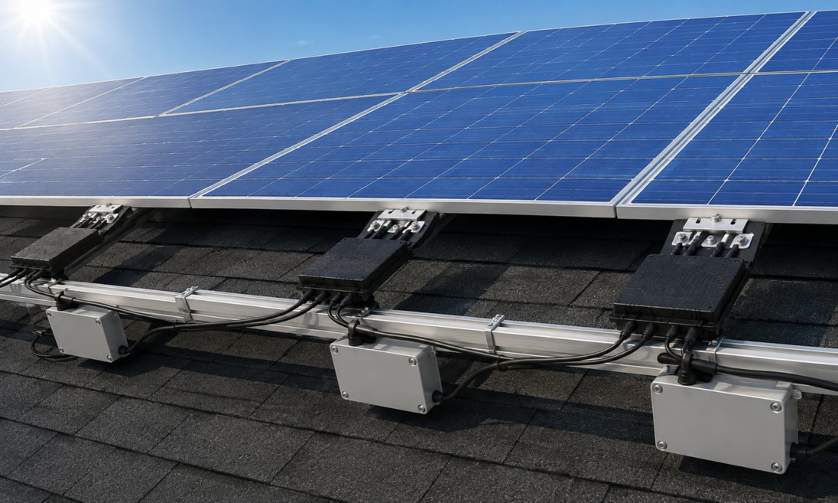
While advanced half-cut panel designs reduce internal cell resistance, complex rooftop layouts subject to heavy, dynamic shadows require active electrical management. Where standard string inverters struggle to balance voltage across partially obstructed strings, Module-Level Power Electronics (MLPE) intervene directly behind each panel.
Performing independent Maximum Power Point Tracking (MPPT) at the individual module level, MLPE hardware prevents a single shaded panel from pulling down the performance of adjacent unshaded modules.
Comparative Evaluation of Inverter Topologies
Selecting between traditional string architectures, DC optimizers, and microinverters requires evaluating the trade-offs between initial capital expenditure (CapEx), system efficiency under shade, and long-term maintenance overhead:
| Parameter | Standard String Inverter | String Inverter + DC Optimizers | Microinverters (MLPE) |
|---|---|---|---|
| Shade Management Level | Array / String Level (Weakest panel bottleneck) | Module-Level DC-to-DC Optimization | Full Module-Level AC Decoupling |
| MPPT Execution | 1 to 4 MPPT channels per central inverter unit | Independent MPPT per individual module | Independent MPPT per individual module |
| Yield Recovery in Partial Shade | Baseline (High losses if bypass diodes do not activate) | High (Recovers up to 20%–25% of lost shade energy) | Maximum (Complete panel independence; zero string drag) |
| System Visibility & Diagnostics | String-level aggregated data | Per-panel DC voltage and energy monitoring | Per-panel AC output and health diagnostics |
| Capital Expenditure (CapEx) | Lowest upfront hardware cost | Moderate upgrade cost (Inverter + Optimizers) | Premium initial equipment investment |
Comparing these topologies highlights why commercial developers evaluating shaded sites increasingly shift away from basic string architectures toward MLPE-enhanced systems to safeguard lifetime energy yields.
DC Power Optimizers: Matching Voltage Across Unbalanced Strings
DC power optimizers such as those manufactured by SolarEdge are installed directly on the racking behind each PV module. Instead of converting DC electricity to AC on the roof, an optimizer acts as a high-efficiency DC-to-DC converter:
- Dynamic Voltage and Current Matching: When a panel becomes partially shaded, its current output drops. The DC optimizer automatically steps down the module’s operating voltage to increase current output, matching the amperage of unshaded modules along the same series string.
- Fixed-String Voltage Architecture: Optimizers adjust individual panel voltages dynamically while maintaining a fixed, optimal DC voltage input to the central inverter. This allows the main inverter to operate at peak efficiency regardless of environmental variations or string length differences.
- Safety and Rapid Shutdown Compliance: In addition to shade recovery, DC optimizers feature automatic rapid shutdown capabilities. If AC grid power is disconnected, optimizers automatically drop individual string voltages to safe levels (1V per panel), protecting maintenance technicians and emergency responders.
Deploying DC power optimizers enables EPCs to design flexible strings across complex multi-pitch commercial roofs without incurring severe mismatch losses.
Microinverters: Full Module Independence for Maximum Yield
Microinverters such as the Enphase IQ series represent the complete decentralization of solar power conversion. Attached directly to each panel, a microinverter converts DC power to grid-compliant AC power right on the roof, eliminating centralized string dependencies:
- Complete Electrical Isolation: Because every module operates as an independent AC power plant, a heavily shaded or dirty panel impacts only its own immediate production. Surrounding panels continue generating 100% of their available potential without being bottlenecked.
- Elimination of High-Voltage DC Strings: Converting power to AC directly at the module removes high-voltage DC cabling across the roof, reducing arc-fault fire risks and simplifying installation compliance for sensitive commercial properties.
- Low Irradiance Start-up Advantage: Microinverters operate at very low DC input voltages, allowing modules to start harvesting energy earlier during morning twilight and under heavy monsoon cloud cover.
Achieving true solar optimization through microinverters ensures that complex rooftops subject to persistent obstructions such as urban commercial buildings with dense HVAC equipment and parapets produce maximum cumulative power output throughout their operating lifecycle.
Sourcing these advanced MLPE technologies through authorized master distributors guarantees long-term product availability, valid factory warranties, and direct technical backing for your engineering teams.
Engineering Best Practices for Rooftop Layouts
While advanced panel architectures and Module-Level Power Electronics provide powerful tools for recovering lost power, the most cost-effective way to manage shading is to prevent it during the initial engineering phase.
Performing rigorous pre-construction site analysis and designing intelligent array layouts allows engineering, procurement, and construction (EPC) teams to eliminate avoidable shadows before a single mounting rail is anchored.
Pre-Construction Shade Modeling and Simulation
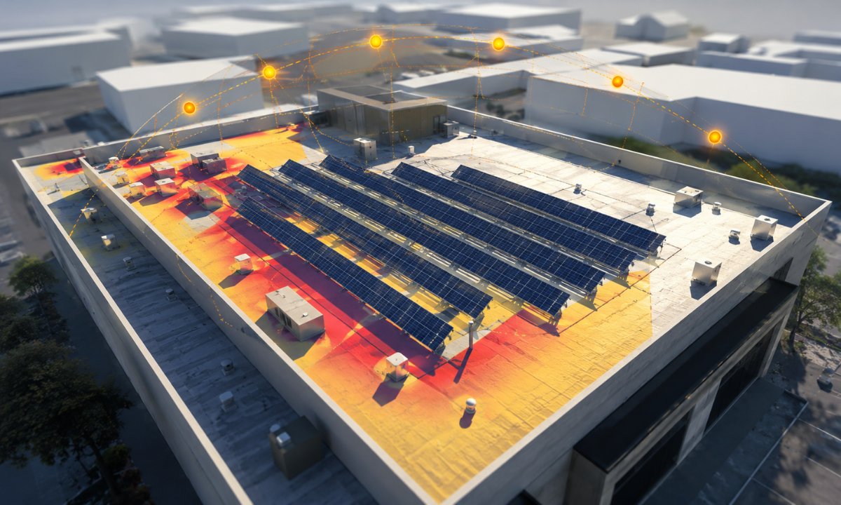
Modern solar engineering relies on sophisticated software modeling to predict shading patterns across every hour of the year. Installing panels based on visual guesswork during a midday site survey often leads to severe unexpected losses during winter months when the sun’s elevation angle drops:
- 3D Solar Simulation and LiDAR Mapping: Utilizing advanced design software such as PVsyst, Helioscope, or Solargraf incorporates drone-assisted LiDAR elevation data to build exact 3D models of surrounding buildings, parapet walls, trees, and rooftop HVAC units. These tools generate detailed Sunpath diagrams to simulate shadow movements across all 365 days of the year.
- Inter-Row Pitch Calculations: On flat commercial rooftops where tilt legs are installed, calculating the precise inter-row pitch distance is mandatory to eliminate self-shading. The minimum row spacing must be derived using the winter solstice sun angle at 10:00 AM and 2:00 PM, ensuring that the front edge of a rear panel row remains completely clear of the shadow cast by the row ahead of it.
- Strategic MPPT Grouping and Sub-String Allocation: When an array spans across areas with varying shade profiles, modules experiencing similar shading patterns must be grouped on dedicated Maximum Power Point Tracking (MPPT) inputs. Mixing shaded and unshaded modules on the same MPPT channel forces the inverter to compromise its voltage tracking, dragging down the performance of the unshaded panels.
- Optimized Panel Mounting Orientation: Aligning panel orientation with the specific physical geometry of surrounding obstacles significantly alters how bypass diodes respond. For example, mounting half-cut modules in a landscape orientation near a parapet wall ensures that a low horizontal shadow covers only the bottom row of cells, allowing the upper half of the panel to continue generating full power.
Simulating these environmental variables in a virtual environment before procurement allows solar developers to identify low-irradiance zones on the roof and allocate those spaces for walkways, inverter mounting stations, or balance-of-system distribution boxes instead of active solar modules.
Mitigating Obstacle Shadows Through Physical Array Placement
Once shading simulation software identifies high-risk zones on a rooftop, design engineers must establish physical buffer zones around fixed obstructions. Leaving a calculated setback distance equal to two to three times the height of an HVAC unit or machine room ensures that high-yield modules operate in permanent full sun.
Furthermore, adjusting tilt angles by a few degrees can often trade a tiny fraction of ideal orientation yield for a significant reduction in inter-row shading, resulting in a higher net energy output for space-constrained commercial projects.
Integrating these layout practices with high-performance hardware guarantees that your array achieves its projected performance ratio (PR) consistently. Sourcing your mounting structures, tilt legs, and shade-tolerant modules through a single authorized distributor simplifies project delivery, ensuring that every physical component on the roof aligns perfectly with your engineering layout plans.
Conclusion
Managing shading across commercial and residential rooftops is not merely an aesthetic or physical concern; it is an active electrical challenge that directly impacts system return on investment (ROI). While unmitigated shadows cause cell mismatch, thermal hot spots, and severe string degradation, deploying modern shade-tolerant hardware and implementing intelligent layout designs protects overall generation yield.
Key Takeaways for Solar Project Developers and EPCs
To ensure that solar arrays operate at peak performance throughout their 25-year design life, engineering teams must combine site-level modeling with advanced equipment selection:
- Conduct 3D Shade Modeling During Feasibility: Utilizing design software to simulate seasonal sun paths identifies high-risk shading zones before mounting structures are anchored, allowing designers to establish necessary physical setbacks around rooftop obstacles.
- Specify Half-Cut and Multi-Busbar Module Architectures: Selecting half-cut cell panels with split junction box designs guarantees that localized shadows on lower module edges leave the upper half of the panel operating at 100% capacity.
- Deploy MLPE Solutions on Heavily Obstructed Sites: Pairing string inverters with DC power optimizers or microinverters decouples individual module performance, preventing a single shaded panel from pulling down an entire series string.
- Source Genuine Equipment Through Authorized Distributors: Procurement through certified master distribution channels guarantees access to tier-1 shade-tolerant modules, DISCOM-compliant inverters, and full manufacturer warranty tracking.
Implementing these engineering controls eliminates unbudgeted performance losses and ensures that commercial solar assets deliver predictable financial returns.
Partner with Sun-AP Ecopower for Advanced Solar Equipment
As India’s premier authorized master distributor and B2B wholesaler, Sun-AP Ecopower supplies EPC contractors, system integrators, and solar developers with tier-1 shade-tolerant solar modules, advanced inverters, and MLPE technologies. Our extensive distribution network delivers genuine factory-backed inventory from world-leading brands including Panasonic, Adani, REC, Enphase, SolarEdge, Sungrow, FIMER, and Deye at competitive wholesale prices.
Whether you are designing a compact residential rooftop or executing a complex commercial and industrial (C&I) project across urban landscapes, our technical team provides balance-of-system (BoS) solutions tailored to your engineering requirements.
Get in Touch for B2B Wholesale Procurement
Contact our technical sales team today to request bulk price quotations, verify stock availability, or consult with our engineers on specialized equipment selection for your upcoming solar projects.
- B2B Direct Line: +91 88844 66393 / +91 98453 50616
- Email Inquiries: marketing@sunapecopower.com / sales@sunapecopower.com
- Official Website: sunapecopower.com
Head Office: Sun-AP Ecopower Pvt. Ltd., No. 393, 2nd Cross, Dollars Colony, JP Nagar 4th Phase, Bengaluru, Karnataka 560078, India.